HSRP, short for Hot Standby Router Protocol, is a first-hop redundancy protocol that allows multiple routers to collectively serve as the default gateway for high-priority host devices/subnetwork. At any given time, one of the routers serves as the active default gateway, while the others act as backups. In the event of the active router’s failure, one of the backup routers takes over the duty of being the default gateway, ensuring high availability for all host devices within that subnetwork.
In this post, I will show you how to configure HSRP on a Cisco router. We will consider a sample network topology and configure HSRP on two routers connecting to host devices so that one router serves as the active default gateway and the other as the backup.
Network Topology
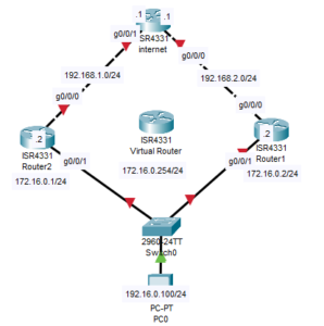
The network topology we will use in this post is depicted below. As shown, it consists of two routers connected to a host device within the 172.16.0.0/24 subnetwork. Both routers are also connected to the internet router. In this demonstration, we will configure HSRP on the two routers so that the PC can access the internet router using either of the two routers as the default gateway.
Download the premade lab file or recreate the network topology shown below on your packet tracer software.

Lab Objectives
In this post, we will complete the following configuration.

- Configure Router R1 to connect to the internet (by configuring default route).
- Configure Router R2 to connect to the internet (By configuring default route).
- Configure static route on the internet router so that it can reply back to the 172.16.0.0 network.
- Implement HSRP on Router R1 with preemption enabled.
- Implement HSRP on Router R2 with a higher priority and preemption enabled.
- Configure the Host PC with appropriate IP settings and set the default gateway to the virtual router IP address.
- Conduct a ping test from the Host PC to the interface ip address of the internet router to verify connectivity.
- Verify HSRP status on Router R1 and R2 to ensure proper failover and standby configurations.
How to configure HSRP on a Cisco Router
Here are steps to configure HSRP on a cisco router considering the network topology above;
Step 1: Configure the interfaces of the routers and default route
On R1
R1(config)#interface g0/0/0
R1(config-if)#ip address 192.168.2.2 255.255.255.0
R1(config-if)#no shut

R1(config-if)#
%LINK-5-CHANGED: Interface GigabitEthernet0/0/0, changed state to up

R1(config-if)#exit
R1(config)#ip route 0.0.0.0 0.0.0.0 192.168.2.1
R1(config)#interface g0/0/1
R1(config-if)#ip address 172.16.0.2 255.255.255.0
R1(config-if)#no shut
The default route configured above will allow R1 to forward any traffic that it does not have route to in the routing table to the internet.
On R2
R2(config)#interface g0/0/0
R2(config-if)#ip address 192.168.1.2 255.255.255.0
R2(config-if)#no shut

R2(config-if)#
%LINK-5-CHANGED: Interface GigabitEthernet0/0/0, changed state to up

R2(config-if)#ip route 0.0.0.0 0.0.0.0 192.168.1.1
R2(config)#interface g0/0/1
R2(config-if)#ip address 172.16.0.1 255.255.255.0
R2(config-if)#no shut
On Internet Router
We have to configure a static route to 172.16.0.0/24 so that the Internet router can reach PC0.
internet(config-if)#interface g0/0/1
internet(config-if)#ip address 192.168.1.1 255.255.255.0
internet(config-if)#no shut
internet(config-if)#exit
internet(config)#ip route 172.16.0.0 255.255.255.0 192.168.1.2
internet(config)#ip route 172.16.0.0 255.255.255.0 192.168.2.2
Step 2: Configure HSRP and Preemption
To configure HSRP on R1 and R2, we need to configure a virtual IP address on the interfaces of the Routers connecting to the 172.16.0.0/24 subnetwork.
As we have labeled in our network topology above, we will be configuring 172.16.0.254 as the virtual IP address on R1 and R2.
On R2
R2(config-if)#standby 1 ip 172.16.0.254
R2(config-if)#standby 1 priority 150
R2(config-if)#
%HSRP-6-STATECHANGE: GigabitEthernet0/0/1 Grp 1 state Speak -> Standby

R2(config-if)#standby 1 preempt
The commands configure a HSRP with a group number of “1” and a priority value of 150. The group number is used to identify the specific HSRP group across all of the routers for which the HSRP configuration is done.
The priority value, on the other hand, is used to determine which switch will become the active router. Generally, the router with a higher priority value will become the active router (active default gateway).
On R1
R1(config-if)#standby 1 ip 172.16.0.254
R1(config-if)#standby 1 preempt
Note: If not configured, Priority is 100 by default
Step 3: Test configuration
To test the HSRP configuration, we need to use the “show standby” command below to view the standby status.
On R2
R2(config)#do show standby
GigabitEthernet0/0/1 - Group 1
  State is Active ←----- State is active
    4 state changes, last state change 03:16:19
  Virtual IP address is 172.16.0.254
  Active virtual MAC address is 0000.0C07.AC01
    Local virtual MAC address is 0000.0C07.AC01 (v1 default)
  Hello time 3 sec, hold time 10 sec
    Next hello sent in 1.516 secs
  Preemption enabled
  Active router is local
  Standby router is 172.16.0.2, priority 100 (expires in 9 sec)
  Priority 150 (configured 150)
  Group name is hsrp-Gig0/0/1-1 (default)
As expected, R2 is in active mode. This is because we configured R2 to have a higher priority value of 150 as opposed to R1, which has a priority value of 100.
On R1
R1(config-if)#do show standby
GigabitEthernet0/0/1 - Group 1
State is Standby ←----- State is standby
9 state changes, last state change 03:16:42
Virtual IP address is 172.16.0.254
Active virtual MAC address is 0000.0C07.AC01
Local virtual MAC address is 0000.0C07.AC01 (v1 default)
Hello time 3 sec, hold time 10 sec
Next hello sent in 2.412 secs
Preemption enabled
Active router is 172.16.0.1, priority 150 (expires in 9 sec)
MAC address is 0000.0C07.AC01
Standby router is local
Priority 100 (default 100)
Group name is hsrp-Gig0/0/1-1 (default)
To further test the configuration, we need to test the route traffic follow from the PC to the internet router.
Remember to configure 172.16.0.254 as the default gateway on the PC. 172.16.0.254 is the virtual IP address of which we configured on both Router 1 and Router2.
On the PC
C:\>tracert 192.168.1.1
Tracing route to 192.168.1.1 over a maximum of 30 hops:
1 0 ms 0 ms 0 ms 172.16.0.1
2 0 ms 0 ms 0 ms 192.168.1.1
Trace complete.
C:\>tracert 192.168.2.1
Tracing route to 192.168.2.1 over a maximum of 30 hops:
1 0 ms 0 ms 0 ms 172.16.0.1
2 0 ms 0 ms 0 ms 192.168.2.1
As seen above, the traffic is passing through R2 because it is the active router.
Then shutdown the interface on R2 and then check if packet will travel through R1
C:\>tracert 192.168.2.1

Tracing route to 192.168.2.1 over a maximum of 30 hops:

  1   0 ms      0 ms      0 ms      172.16.0.2
  2   *         0 ms      *         Request timed out.

Trace complete.

C:\>tracert 192.168.1.1

Tracing route to 192.168.1.1 over a maximum of 30 hops:

  1   0 ms      0 ms      0 ms      172.16.0.2
  2   0 ms      *         0 ms      192.168.1.1
Related:
How to configure HSRP on a Layer 3 Switch

I am a passionate Networking Associate specializing in Telecommunications.
With a degree in Electronic engineering, I possess a strong understanding of electronic systems and the intricacies of telecommunications networks. I gained practical experience and valuable insights working for a prominent telecommunications company.
Additionally, I hold certifications in networking, which have solidified my expertise in network architecture, protocols, and optimization.
Through my writing skills, I aim to provide accurate and valuable knowledge in the networking field.
Connect with me on social media using the links below for more insights.
You can contact me using [email protected] or connect with me using any of the social media account linked below