When dealing with multiple VLANs that span two or more switches, a trunk link comes in handy to segregate traffic for specific VLANs as it travels across the cables that connect one switch to another. A Trunk Link is established by configuring the trunk port on each of the switches attempting to form a trunk link.
Creating a trunk link is akin to creating a virtual cable (link) on the Layer 2 cable that connects one switch to another, ensuring that each of these virtual cables carries traffic for a particular VLAN.
There are various scenarios where it becomes necessary for host devices on different switches to belong to the same VLAN. For example, in a company with multiple branches, each branch’s marketing department may require its VLAN for efficient network management.
In this post, I will demonstrate how to Configure Trunk Port on Multilayer Switch and then establish a trunk link between the layer 3 switch and the Layer 2 switch. This configuration will enable PCs attached to different switches but within the same VLAN to communicate through the trunk link.

Here is a video showing How To Configure Trunk Port on Multilayer Switch in Packet Tracer;
Network Topology
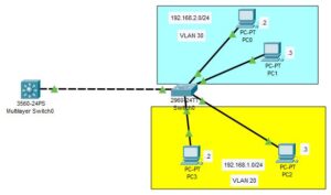
As depicted below, the network topology used for this demonstration consists of one Layer 3 switch, one Layer 2 switch, and multiple PCs connected to the Layer 2 switch, segmented into VLAN 20 and VLAN 30.

Configuration Objectives:
- Configure trunk ports on the multilayer switch.
- Configure trunk ports on the Layer 2 switch to establish a trunk link with the Layer 3 switch.
- Segment the LAN into two VLANs and enable routing between these VLANs.
- Test the configuration.
Command to Configure Trunk port on Layer 3 switch;
To configure trunk port in a layer 3 switch, enter the following commands from the interface configuration mode;
Switch(config-if)#switchport trunk encapsulation dot1q
Switch(config-if)#switchport mode trunk
Configuration
The following are the configuration you need to complete on the network components to achieve the above objective.

Multilayer Switch
Creating VLANs
Enter the following command to create the two vlans;
Switch>en
Switch#conf t
Switch(config)#vlan 20
Switch(config-vlan)#vlan 30
Switch(config-vlan)#exit
Confirms the vlans…
Switch(config)#do show vlan brief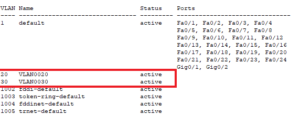
Creating the trunk port
Enter the following commands to create trunk port on the layer 3 switch;
Switch(config)#int fa0/1
Switch(config-if)#switchport trunk encapsulation dot1q
Switch(config-if)#switchport mode trunk
Creating SVIs
Enter the following commands to create SVIs and assign IP addresses to them;
Switch(config-if)#int vlan 20
Switch(config-if)#ip address 192.168.1.1 255.255.255.0
Switch(config-if)#no shut
Switch(config-if)#int vlan 30
Switch(config-if)#ip address 192.168.2.1 255.255.255.0
Switch(config-if)#no shut
Switch(config-if)#exit
Enable IP Routing
Enter the following commands to enable Ip routing on the layer 3 Switch;
Switch(config)#ip routing
Switch(config)#do write
Switch 0
Creating Trunk port
Enter the following commands to create the trunk port on the layer 2 switch;
Note: This configuration completes the creation of Trunk link between Switch0 and the Layer 3 switch
Switch>en
Switch#conf t
Switch(config-if)#int fa0/1
Switch(config-if)#switchport mode trunk
Switch(config-if)#exit
Creating VLANs
Enter the following commands to create VLAN 20 and VLAN 30 on the layer 2 switch;
Switch(config)#vlan 20
Switch(config-vlan)#vlan 30
Creating Access ports
Enter the following commands to create access ports on switch0;
Switch(config)#int fa0/2
Switch(config-if)#switchport mode access
Switch(config-if)#switchport access vlan 20
Switch(config-if)#int fa0/3
Switch(config-if)#switchport mode access
Switch(config-if)#switchport access vlan 20
Switch(config-if)#int fa0/4
Switch(config-if)#switchport mode access
Switch(config-if)#switchport access vlan 30
Switch(config-if)#int fa0/5
Switch(config-if)#switchport mode access
Switch(config-if)#switchport access vlan 30
Configure the host devices
Configure the host with IP address as labeled in the network topology showed above.
Note: The host devices in VLAN 20 have their own subnetwork, and the host devices on VLAN have their own subnetwork. So while making your IP address configuration, observe it.
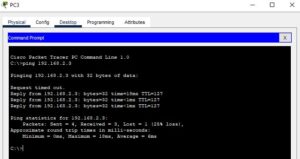
Testing
To test the configuration, I have pinged from PC3 to PC1 and as you can see from the image below, PC1 was reachable;

I am a passionate Networking Associate specializing in Telecommunications.
With a degree in Electronic engineering, I possess a strong understanding of electronic systems and the intricacies of telecommunications networks. I gained practical experience and valuable insights working for a prominent telecommunications company.
Additionally, I hold certifications in networking, which have solidified my expertise in network architecture, protocols, and optimization.
Through my writing skills, I aim to provide accurate and valuable knowledge in the networking field.
Connect with me on social media using the links below for more insights.
You can contact me using [email protected] or connect with me using any of the social media account linked below