The Network Time Protocol (NTP) is a protocol used for synchronizing time across various network devices within a network.
By default, network devices rely on their individual hardware clocks, leading to time disparities that not only deviate from real-world time but also vary among different devices.
Manually configuring time on each network device is a viable solution to address time variations. However, when we have large networks, manual configuration becomes impractical and lacks scalability. An efficient and automated alternative is to leverage the capabilities of the Network Time Protocol.
NTP facilitates the synchronization of time across network devices by connecting them to a designated and reliable time server—commonly referred to as an NTP server.

In this blog post, I will show you how to Configure NTP Server in Packet Tracer.
The importance of maintaining accurate time on network devices extends beyond the mere alignment of clocks. Precise timekeeping proves invaluable in troubleshooting errors within network devices, enabling a more insightful interpretation of syslog messages—a critical aspect of network management and diagnostics.

Related Post
- How to Configure Syslog Server in Packet Tracer
- How to Configure a Web Server in Packet Tracer
- How to Configure TFTP Server In Packet Tracer
- How To Configure FTP Server in Cisco Packet tracer
- How To Configure Email Server in Cisco Packet Tracer
- How to Configure DNS Server On Cisco Packet Tracer
Network Topology
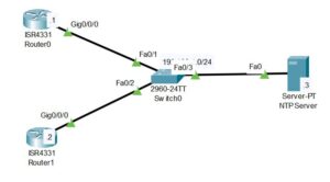
The network topology that we will be making use of in this post is shown below. As you can see, it consists of two routers, a layer 2 switch, and an NTP server.
In this demonstration, we will configure the two routers to use the server as their NTP server. By default, the NTP server has an accurate time, like the timezone and exact time of whatever country you are residing in.

Here is a vidoe on how to configure NTP server in packet tracer;
How to Configure NTP Server in Packet Tracer
Here are steps to configure NTP server in packet tracer;
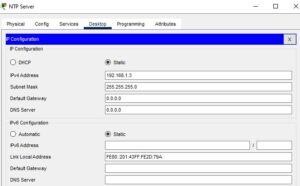
Step 1: Configure the Interface of the NTP server & NTP Client.
The first thing is to assign an IP address to the interface of the NTP server and NTP clients (Router1 and Router0).
Router 0
Router>enable
Router#configure terminal
Router(config)#hostname R0
R0(config)#interface g0/0/0
R0(config-if)#ip address 192.168.1.1 255.255.255.0
R0(config-if)#no shut
Router1
Router>enable
Router#configure terminal
Router(config)#hostname R1
R1(config)#interface g0/0/0
R1(config-if)#ip address 192.168.1.2 255.255.255.0
R1(config-if)#no shut
NTP Server
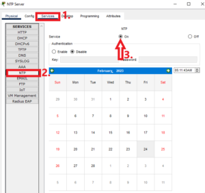
Step 2: Enable the NTP service on the NTP server
Although NTP is enabled by default on the server in the packet tracer, confirm that by going to services>NTP.
Step 3: Check the Default time on the NTP Clients
Before we configure the NTP server on the two routers, it is good to check the default hardware times and see how they vary with the real time. The command below does this:
Router0
R0#show clock detail
*0:22:15.90 UTC Mon Mar 1 1993
Time source is hardware calendar
Router1
R1#show clock detail
*0:22:46.342 UTC Mon Mar 1 1993
Time source is hardware calendar
Step 4: Configure the NTP Client
To configure the NTP clients to obtain their time from an accurate time server using NTP, we need to specify the IP address of the server and the time zone.
Router0
R0>enable
R0#configure terminal
R0(config)#clock timezone WAT 1
R0(config)#ntp server 192.168.1.3
Router1
R1>enable
R1#configure terminal
R1(config)#clock timezone WAT 1
R1(config)#ntp server 192.168.1.3
In the above commands, I configured the timezone to be West African time (WAT), which is the time zone of my country, Nigeria. WAT has an offset of +1 from UTC.
Step 5: Verify the configuration
After applying the commands in step 4 to each of the routers, it takes some time for the routers to synchronize their time with that of the NTP server. We can check whether the time has been synchronized by using the command “show ntp association.” An offset value of 0.00 indicates that the time has been synchronized with that of the server.
Router0
R0(config)#do show ntp association

address         ref clock       st   when     poll    reach  delay          offset            disp
*~192.168.1.3   127.127.1.1     1    15       16      37     1.00           0.00              0.12
 * sys.peer, # selected, + candidate, - outlyer, x falseticker, ~ configured
Router1
R1(config)#do show ntp association

address         ref clock       st   when     poll    reach  delay          offset            disp
*~192.168.1.3   127.127.1.1     1    8        16      377    0.00           0.00              0.12
 * sys.peer, # selected, + candidate, - outlyer, x falseticker, ~ configured
Now, we check the updated time on the NTP clients by using “show clock detail”
Router1
R1#show clock detail
5:37:23.618 WAT Fri Feb 24 2023
Time source is NTP
Router0
R0#show clock detail
5:38:51.373 WAT Fri Feb 24 2023
Time source is NTP
That is all for this post. In the next post, we will be showing you how to configure NTP authentication.
Related Post
- How to Configure Syslog Server in Packet Tracer
- How to Configure a Web Server in Packet Tracer
- How to Configure TFTP Server In Packet Tracer
- How To Configure FTP Server in Cisco Packet tracer
- How To Configure Email Server in Cisco Packet Tracer
- How to Configure DNS Server On Cisco Packet Tracer

I am a passionate Networking Associate specializing in Telecommunications.
With a degree in Electronic engineering, I possess a strong understanding of electronic systems and the intricacies of telecommunications networks. I gained practical experience and valuable insights working for a prominent telecommunications company.
Additionally, I hold certifications in networking, which have solidified my expertise in network architecture, protocols, and optimization.
Through my writing skills, I aim to provide accurate and valuable knowledge in the networking field.
Connect with me on social media using the links below for more insights.
You can contact me using [email protected] or connect with me using any of the social media account linked below