This article will guide you on how to Configure Dynamic NAT on Cisco Router using Packet Tracer.
Network Address Translation (NAT) is a crucial algorithm utilized to map private IP addresses to public IP addresses, enabling routing over the internet.
Due to the substantial increase in the number of internet users over the past few years, the availability of IPv4 addresses has nearly depleted. As a short-term solution to address the scarcity of IP addresses, the adoption of Network Address Translation (NAT) and Classless Inter-Domain Routing (CIDR) has become imperative.
There are three distinct types of NAT: static NAT, dynamic NAT, and PAT.

In contrast to static NAT, which we discussed in our previous post, dynamic NAT offers more efficient IP address management. In dynamic NAT, the public IP address mapped to a private address is automatically released when not in use, allowing it to be reassigned to another private IP address requiring internet communication. Therefore, while static NAT involves permanent mappings, dynamic NAT involves temporary mappings of a public IP address to a private IP address.
The NAT-enabled router is configured with a pool of public addresses, which it maps to private IP addresses based on first-come, first-served. Once the configured pool of public addresses has been exhausted, a situation know as NAT pool exhaustion will result, and any other private IP address requesting to send traffic outside the LAN will need to wait for an IP address to be released.

Network Topology
The network topology for this demonstration comprises a Cisco router, four host devices attached to the router, and a server residing over the internet. In this demonstration, we will be configuring NAT to map the private IP addresses of the host devices to dynamic public addresses.
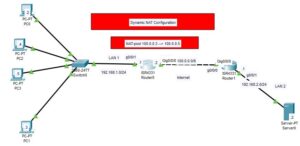
Note: The private IP addresses assigned to the host devices are called local IP addresses. While NAT-pool we are going to dynamically mapped to the inside-local IP addresses are called global IP addresses.

How To Configure Dynamic NAT on Cisco Router
The steps to configure Dynamic NAT involve;
- Creating an access list of IP addresses that need to be translated or mapped
- Creating a NAT pool
- Mapping access lists with pools
- Define the inside and outside interfaces.
Step 1: Create Access-list of IP addresses
Enter the following commands to create an access list of IP addresses that need to be mapped to a public IP address: In this case, we need to map all IP addresses originating from the network. 192.168.1.0/24.
R0>en
R0#conf t
Enter configuration commands, one per line.  End with CNTL/Z.
R0(config)#access-list 1 permit 192.168.1.0 0.0.0.255
R0(config)#access-list 1 deny any
The above command will allow only the IP addresses from the 192.168.1.0/24 network to be mapped to the pool we are going to create in the next step.
Note: Because this ACL is not going to be applied to an interface, no traffic will be denied from traversing the router. The configuration simply means that traffic that is not from the access list will not be mapped with a dynamic IP address. We have written a separate post on the access control list.
Step 2: Create NAT pool
Enter the following command to create the Pool of Public IP address which is to be mapped to private IP addresses.
R0(config)#ip nat pool POOL_1 100.0.0.3 100.0.0.5 netmask 255.0.0.0Note: POOL_1 is an arbitrary name given to our NAT pool, and the range 100.0.0.3–100.0.0.5 is the IP address pool, while 255.0.0.0 is the subnet mask for the network 100.0.0.0.
Step 3: Map the Access list with the Pool
The commands below will map the Access list we created in step 1 to the Nat pool we create in step 2.
R0(config)#ip nat inside source list 1 pool POOL_1Step 4: Define the inside and outside interfaces
Finally, we need to define the interfaces that are connected to the local network and the interfaces that are connected to the global network. This is achieved with the following commands:
R0(config)#int g0/0/1
R0(config-if)#ip nat inside
R0(config-if)#int g0/0/0
R0(config-if)#ip nat outside
R0(config-if)#do write
Step 5: Test the configuration
Once you have completed the above configuration, you need to test connectivity between the PC existing on the 192.168.1.0/24 network and the server. As shown in the image below, I have pinged from PC2 to the server, and as you can see, I got a reply.

To further confirm Dynamic NAT configuration on the router, we ran the following show command;
R0(config-if)#do show ip nat translationsAnd the we obtained the following results;

Related:

I am a passionate Networking Associate specializing in Telecommunications.
With a degree in Electronic engineering, I possess a strong understanding of electronic systems and the intricacies of telecommunications networks. I gained practical experience and valuable insights working for a prominent telecommunications company.
Additionally, I hold certifications in networking, which have solidified my expertise in network architecture, protocols, and optimization.
Through my writing skills, I aim to provide accurate and valuable knowledge in the networking field.
Connect with me on social media using the links below for more insights.
You can contact me using [email protected] or connect with me using any of the social media account linked below