Access Control Lists (ACLs) play a pivotal role in network security, facilitating the management of traffic flow within a network. The configuration of ACLs allows for the specification of permissions of traffic to subnetwork or individual host devices, such as servers.
To create an ACL, one must define permissions (rules) on the router or Layer 3 switch that is close to the designated host or nearest to the source host, depending on the type of ACL being configured.
There are various types of ACLs, including standard ACL, standard-numbered ACL, extended ACL, and extended-numbered ACL, each of which is covered in a separate post below.
- Standard Numbered ACL Configuration in Packet Tracer
- Extended Numbered ACL Configuration in Packet Tracer
- Extended Named ACL Configuration in Packet Tracer
Similar to the way we configure ACL on Cisco routers, we can also configure ACL on layer 3 switch and control traffic flow in our network. The only difference is that we need to enable IP routing and turn the layer 3 switchport to a routed port while configuring the static route on the layer 3 switch.

Network Topology
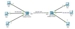
The network topology we will be making use of is as shown below. As you can see, it consists of two layer 3 switches and three PCs, each connected to the layer 3 switch.

Here is a video on how to configure ACL on layer 3 switch;
Configuration Objectives
The objective of this configuration is to:
- Configure a Standard Named ACL on Multilayer Switch0 to deny traffic from PC0 to the network (192.168.2.0/24) while permitting all other traffic.
- Configure a Standard Named ACL on Multilayer Switch 1 to deny traffic from PC3 to the network (192.168.3.0/24) while permitting all other traffic.
How to Configure ACL On Layer 3 Switch
Here are steps to configure ACL on layer 3 Switch;

Step 1: Configure static Route on each layer 3 switch
Enter the following command on the 2 layer 3 switch to configure the static route. If you are curious to know what each command does, you can read our post on how to configure a static route on the Layer 3 switch.
Remember to use the IP address assigned to the vlan1 as the default gateway IP address for PCS attached to each of the layer 3 switches.
Multilayer Switch0
Switch#conf t
Switch(config)#int vlan 1
Switch(config-if)#ip address 192.168.2.1 255.255.255.0
Switch(config-if)#no shut
Switch(config-if)#exit
Switch(config)#ip routing
Switch(config)#int fa0/1
Switch(config-if)#no switchport
Switch(config-if)#ip address 192.168.1.2 255.255.255.0
Switch(config-if)#no shut
Switch(config-if)#exit
Switch(config)#ip route 192.168.3.0 255.255.255.0 192.168.1.1
Multilayer Switch1
Switch#conf t
Switch(config)#int vlan 1
Switch(config-if)#ip address 192.168.3.1 255.255.255.0
Switch(config-if)#no shut
Switch(config-if)#exit
Switch(config)#ip routing
Switch(config)#int fa0/1
Switch(config-if)#no switchport
Switch(config-if)#ip address 192.168.1.1 255.255.255.0
Switch(config-if)#no shut
Switch(config-if)#exit
Switch(config)#ip route 192.168.2.0 255.255.255.0 192.168.1.2
Step 2: Configure ACL on Multilayer Switch0 to deny traffic from PC0.
Switch>en
Switch#conf t
Switch(config)#ip access-list standard FILTER_ACL
Switch(config-std-nacl)#deny 192.168.3.2
Switch(config-std-nacl)#permit any
Switch(config-std-nacl)#int fa0/1
Switch(config-if)#ip access-group FILTER_ACL in
The commands above create an ACL with the name Filter_ACL and define a rule that denies traffic from 192.168.3.2 and permits all other traffic. The last command applies the ACL to the FA0/1 interface of Multilayer Switch 0.
Step 3: Configure ACL on Multilayer Switch1 to deny traffic from PC3.
Switch>en
Switch#conf t
Switch(config)#ip access-list standard FILTER_ACL2
Switch(config-std-nacl)#deny 192.168.2.2
Switch(config-std-nacl)#permit any
Switch(config-std-nacl)#int fa0/1
Switch(config-if)#ip access-group FILTER_ACL2 in
The commands above create an ACL with the name Filter_ACL2 and define a rule that denies traffic from 192.168.2.2 and permits all other traffic. The last command applies the ACL to the FA0/1 interface of Multilayer Switch1
Step 4: Test the configuration
To test the configuration, I have pings from PC0 to PC4, and as you can see below, the pings failed because of the ACL rule configured on Multilayer Switch 0.
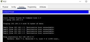
Also, I have pinged from PC3 to PC0, and as you can see, the ping failed because of the ACL rule configured on multilayer switch 1.

Related Posts;
- Standard Numbered ACL Configuration in Packet Tracer
- Extended Numbered ACL Configuration in Packet Tracer
- Extended Named ACL Configuration in Packet Tracer

I am a passionate Networking Associate specializing in Telecommunications.
With a degree in Electronic engineering, I possess a strong understanding of electronic systems and the intricacies of telecommunications networks. I gained practical experience and valuable insights working for a prominent telecommunications company.
Additionally, I hold certifications in networking, which have solidified my expertise in network architecture, protocols, and optimization.
Through my writing skills, I aim to provide accurate and valuable knowledge in the networking field.
Connect with me on social media using the links below for more insights.
You can contact me using [email protected] or connect with me using any of the social media account linked below