A Switch Virtual Interface (SVI) is a virtual interface configured on the Layer 3 switch to act as the interface used by all host devices connected to the Layer 3 switch for transmitting their traffic to other subnetworks. The SVI in Layer 3 switches is equivalent to a router interface, where an IP address is configured and utilized as the default gateway interface for all host devices within that subnetwork.
A Layer 3 switch, often referred to as a multilayer switch, is capable of implementing both switching and routing functions. When a Layer 3 switch is employed for routing functions, an IP address is configured to an SVI on the Layer 3 switch. This IP address then serves as the default gateway for all host devices attached to that virtual interface.
In this post, I will demonstrate How To Configure SVI On a Layer 3 Switch. This configuration enables traffic originating from PCs attached to the Layer 3 switch to traverse to other subnetworks or the internet.
Let’s dive in!

Network Topology
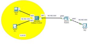
The network topology we are going to be making use of is as shown in the image below. As you can see, it consists of one layer 3 switch with two PCs attached to it and a router with one PC attached to it.
I have already completed the IP address configuration on the router interfaces and on the PCs. I have also completed the static route configuration on the router. We have a separate post on how to configure a static route and also how to configure an IP address on the router interface.

How To Configure SVI On Layer 3 Switch
Here are steps To Configure SVI On multilayer switch;
Step 1: Create SVI
Enter the the following command on the multilayer switch to create SVI;

Switch>en
Switch#conf t
Switch(config)#hostname SW1
SW1(config-vlan)#int vlan 20
SW1(config-if)#ip address 192.168.1.1 255.255.255.0
SW1(config-if)#no shut
The commands above Creates an SVI on the layer 3 switch and assigns the IP address; 192.168.1.1 to it.
Step 2: Configure Access port
In step 1 above, we created VLAN 2o, so we need to give the host devices access to this vlan for them to utilize the SVI we created to route their traffic to other subnetworks. We can achieve this by configuring the access port.
Enter the following command to configure the access port on the Layer 3 switch:
SW1(config)#int fa0/2
SW1(config-if)#switchport mode access
SW1(config-if)#switchport access vlan 20
SW1(config-if)#int fa0/3
SW1(config-if)#switchport mode access
SW1(config-if)#switchport access vlan 20
Step 3: Configure Static route
As shown on the network topology above, the layer 3 switch is using fa0/1 interface to connect to the router, we need to assign IP address to this interface and configure static route on the layer 3 switch.
Enter the following command to configure static route;
SW1(config-if)#int fa0/1
SW1(config-if)#no switchport
SW1(config-if)#ip address 192.168.2.1 255.255.255.0
SW1(config-if)#no shut
SW1(config-if)#exit
SW1(config)#ip routing
SW1(config)#ip route 192.168.3.0 255.255.255.0 192.168.2.2
An alternative way to do this is to configure OSPF on the Layer 3 switch.
Step 4: Test connectivity
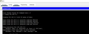
Once you have created the SVI and configured the static route on the layer 3 switch, you can test your configuration by pinging from the PC attached to the layer 3 switch to the PC attached to the router.
The image below shows a ping reply from PC2 to PC1.

I am a passionate Networking Associate specializing in Telecommunications.
With a degree in Electronic engineering, I possess a strong understanding of electronic systems and the intricacies of telecommunications networks. I gained practical experience and valuable insights working for a prominent telecommunications company.
Additionally, I hold certifications in networking, which have solidified my expertise in network architecture, protocols, and optimization.
Through my writing skills, I aim to provide accurate and valuable knowledge in the networking field.
Connect with me on social media using the links below for more insights.
You can contact me using [email protected] or connect with me using any of the social media account linked below