Similar to a router, a Layer 3 switch can route traffic using Layer 3 information.
A layer 3 switch is a device that can perform both routing and switching functions. We simply need to enable IP routing on the switch interface when we want to use it for routing purposes. It performs switching by default.
To enable communication between PCs or host devices located on one side of a layer 3 switch and those located on a neighboring layer 3 switch, static routes need to be configured on each switch to build up the routing table.
In this post, I will be showing you how to configure static routes on a Cisco Layer 3 switch. In our past posts, we covered static route configuration on a Cisco router. However, static route configuration on a layer 3 switch is slightly different from what is done on a Cisco router, but we will clarify everything in this post.

Network Topology
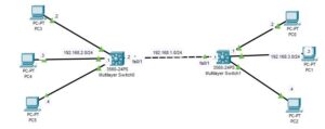
The network topology we will be using in this post is shown below. As you can see, it consists of two layer 3 switches and three PCs connected to each of the layer 3 switches.

Here is a vidoe on how to configure static route on a cisco layer 3 switch;
How to Configure a Static Route on a Cisco Layer 3 Switch
There are two ways in which you can configure the static route on the layer 3 switch: either using the graphics user interface (GUI) or using the command line interface (CLI). In this post, we will be showing you how to do that using the CLI.
Here are the steps to Configure Static Route On Cisco Layer 3 Switch:

Step 1: Assign IP addresses to SVI
For the layer 3 switch to implement routing functions, we need to assign an IP address to a SVI on the switch. All the host devices attached to the switch will utilize this IP address as the default gateway IP address.
The SVI is normally configured on VLAN interfaces, and by default, VLAN 1 exists on every switch, so we will utilize it.
Multilayer Switch0
Enter the following command to create the SVI on the Multilayer Switch:
Switch#conf t
Switch(config)#int vlan 1
Switch(config-if)#ip address 192.168.2.1 255.255.255.0
Switch(config-if)#no shut
Multilayer Switch1
Enter the following command to create the SVI on the Multilayer Switch1;
Switch#conf t
Switch(config)#int vlan 1
Switch(config-if)#ip address 192.168.3.1 255.255.255.0
Switch(config-if)#no shut
Step 2: Enable IP Routing
By default, IP routing is not enabled on the layer 3 switch. Enter the following command to enable IP routing on each of the layer 3 switches:
Switch>enable
Switch#conf t
Switch(config)#ip routing
Remember to run the above command on each of the layer 3 switches.
Step 3: Assign IP address to the fa0/1 interface of layer 3 switch.
As indicated in the network topology above, the two layer 3 switch uses fa0/1 interface to connect to each other.
By default, layer 3 switch ports function as switchports and therefore do not accept IP addresses. To change them to routed ports, we need to run the command “no switchport” on the specific interface to which we want to assign an IP address.
Multilayer Switch0
Enter the following command to configure the IP address for the fa0/1 interface of Multilayer Switch0:
Switch>en
Switch#conf t
Switch(config)#int fa0/1
Switch(config-if)#no switchport
Switch(config-if)#ip address 192.168.1.2 255.255.255.0
Switch(config-if)#no shut
Multilayer Switch1
Enter the following command to assign an IP address to the fa0/1 interface of Multilayer Switch 1:
Switch>en
Switch#conf t
Switch(config)#int fa0/1
Switch(config-if)#no switchport
Switch(config-if)#ip address 192.168.1.1 255.255.255.0
Switch(config-if)#no shut
Step 4: Assign Ip Address to the PCs
The IP addresses of each of the PCs have been shown in the network diagram below.
Configure the IP addresses appropriately for each of the PCs. Remember to use the IP address of the SVIs as the default gateway IP address for each of the PCs. (that is, 192.168.2.1 for PC 3, PC 4, PC 5, and 192.168.3.1 for PC 0, PC 1, PC 2).
Step 5: Configure the static route
Multilayer Switch0
Enter the following command to configure a static route on Multilayer Switch:
Switch>en
Switch#config ter
Switch(config)#ip route 192.168.3.0 255.255.255.0 192.168.1.1
Multilayer Switch1
Enter the following command to configure static route on Multilayer Switch1;
Switch>en
Switch#confi ter
Switch(config)#ip route 192.168.2.0 255.255.255.0 192.168.1.2
Step 6: Verify connectivity.
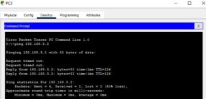
Open the command prompt on PC4 and ping the IP address of PC0. As you can see below, we got a reply:

I am a passionate Networking Associate specializing in Telecommunications.
With a degree in Electronic engineering, I possess a strong understanding of electronic systems and the intricacies of telecommunications networks. I gained practical experience and valuable insights working for a prominent telecommunications company.
Additionally, I hold certifications in networking, which have solidified my expertise in network architecture, protocols, and optimization.
Through my writing skills, I aim to provide accurate and valuable knowledge in the networking field.
Connect with me on social media using the links below for more insights.
You can contact me using [email protected] or connect with me using any of the social media account linked below
Thіs post presents clear idea for the new student in networking, that truly how to do blogging and sіte-building.