Layer 3 switch, often referred to as multilayer switch, are switches that perform both routing and switching functions. By default, layer 3 switches can perform switching functions; however, for a layer 3 switch to perform routing functions, we need to enable IP routing on the switch interfaces from global configuration mode.
In our previous post, we showed how to configure a static route on a layer switch. Today, we are showing how to configure OSPF on the Layer 3 switch in the packet tracer.
OSPF is a dynamic routing protocol that uses a link-state algorithm to build the routing table. OSPF learns about the network’s topology by constructing a connectivity map using OSPF costs.
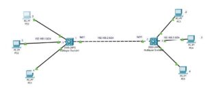
Network Topology
The network topology we will be using in this post is shown below. As you can see, it consists of two layer 3 switches and three PCs connected to each of the layer 3 switches.

How To Configure OSPF on Multilayer Switch
Configuring OSPF on a Layer 3 switch is similar to OSPF configuration on a router, except that you need to enable IP routing on the Layer 3 switch and also turn the switchports into routed ports.

Here is a step-by-step guide on how to configure OSPF on a layer switch:
Step 1: Assign IP addresses to SVI
For the layer 3 switch to perform routing, an IP address needs to be assigned to the switch. This IP address will serve as the default gateway IP address for all host devices existing on such a subnetwork.
The SVI is normally configured on VLAN interfaces, and by default, VLAN 1 (native vlan) exists on every switch, so we will utilize it. However, you can create another VLAN if you want, but that will necessitate trunk port configuration and access port configuration.

Here is how you can assign IP address to SVI on each of the multilayer switch;
Multilayer Switch0
Enter the following command to create the SVI on the Multilayer Switch0:
Switch>en
Switch#conf t
Switch(config)#hostname SW0
SW0(config)#int vlan1
SW0(config-if)#ip address 192.168.3.1 255.255.255.0
SW0(config-if)#no shut
Multilayer Switch1
Enter the following command to create the SVI on the Multilayer Switch1;
Switch>en
Switch#conf t
Switch(config)#hostname SW1
SW1(config)#int Vlan1
SW1(config-if)#ip address 192.168.1.1 255.255.255.0
SW1(config-if)#no shut
Step 2: Enable IP Routing
By default, IP routing is not enabled on the layer 3 switch.
Enter the following command on SW0 to enable IP routing:
SW0(config)#ip routingDo same on SW1 to enable IP routing;
SW(config)#ip routingStep 3: Assign IP address to the fa0/1 of each of the switch
As shown in the network topology above, SW0 connects to SW1 with the fao/1 interface, and SW1 also connects to SW0 with the fa0/1 interface. We need to assign an IP address to each of these interfaces. To do that, we need to change the interface from switchport to routed port.
Here are the commands to change the port to a routed port and assign an IP address to it:
Multilayer Switch0
SW0>en
SW0#conf t
SW0(config)#int fa0/1
SW0(config-if)#no switchport
SW0(config-if)#ip address 192.168.2.1 255.255.255.0
SW0(config-if)#no shut
Multilayer Switch1
SW1>en
SW1#conf t
SW1(config)#int fa0/1
SW1(config-if)#no switchport
SW1(config-if)#ip address 192.168.2.2 255.255.255.0
SW1(config-if)#no shut
Step 4: Assign an IP address to the PCs
Assign an IP address to each of the PCs as labeled in the network topology above. Remember to configure the IP address assigned to the SVI as the default gateway for the PCs. That is 192.168.1.1 is the default gateway ip address for PC 0, PC 1, PC 2, and 192.168.3.1 is the default gateway ip address for PC 3, PC 4, and PC 5.
Step 5: Configure OSPF
Multilayer Switch1
Enter the following command to configure a OSPF on SW0:
SW1(config)#router ospf 1
SW1(config-router)#network 192.168.1.0 0.0.0.255 area 0
SW1(config-router)#network 192.168.2.0 0.0.0.255 area 0
Multilayer Switch0
Enter the following command to configure a OSPF on SW1:
SW0(config)#router ospf 1
SW0(config-router)#network 192.168.3.0 0.0.0.255 area 0
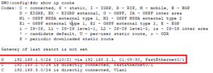
SW0(config-router)#network 192.168.2.0 0.0.0.255 area 0To confirm that OSPF configuration worked, enter the following command;
SW0>en
SW0#config t
SW0(config)#do show ip route
OSPF can be confirmed as shown in the image below;
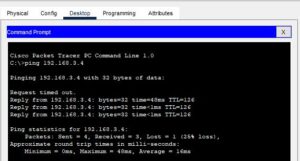
Step 6: Verify connectivity.
Open the command prompt on PC0 and ping the IP address of PC5 to verify connectivity. As shown in the image below, we got a reply.
Related Content;
- How to Configure OSPF Default Route on a Cisco Router
- How to Configure OSPF DR and BDR
- How to Configure OSPF Passive Interface on Cisco Router
- How to Configure OSPF Backbone Area | How to Configure OSPF Area 0
- How to Configure OSPF Multi-Area
- Configuring OSPF Hello Timer
- Redistributing Static Routes into OSPF: Explained With Example

I am a passionate Networking Associate specializing in Telecommunications.
With a degree in Electronic engineering, I possess a strong understanding of electronic systems and the intricacies of telecommunications networks. I gained practical experience and valuable insights working for a prominent telecommunications company.
Additionally, I hold certifications in networking, which have solidified my expertise in network architecture, protocols, and optimization.
Through my writing skills, I aim to provide accurate and valuable knowledge in the networking field.
Connect with me on social media using the links below for more insights.
You can contact me using [email protected] or connect with me using any of the social media account linked below