Hot Standby Routing Protocol (HSRP) is a Cisco proprietary First Hop Redundancy Protocol designed to enhance network reliability by enabling multiple routers to collectively serve as the default gateway for host devices within a subnet. The primary goal of HSRP is to establish redundant connections to the internet for a subnetwork, thereby ensuring a highly available network for all connected devices residing in that subnetwork.
HSRP operates by designating one router as the active default gateway, with the others standing by as backups. This ensures continuous network operation even in the event of a failure of the active router.
While routers are conventionally employed for HSRP configuration, Layer 3 switches can also serve this purpose.
In this post, I will show you how to configure HSRP on a Layer 3 switch. We will configure virtual IP addresses on the two layer 3 switches that are exiting our network so that PCs on our local area network can use these IP addresses as their default gateway rather than the IP addresses configured on the interfaces of the switches.

Let’s dive in.
Network Topology
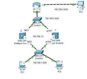
The network topology we will be using is shown in the image below. As you can see, it comprises two layer 3 switches, two layer 2 switches, a router, and host devices.

In this demonstration, we will configure HSRP on the two layer 3 switches so that the hosts residing on the 192.168.1.0/24 subnetwork can use the two layer 3 switches as their redundant default gateway.
Note: I have completed configuring IP address to the interfaces of the router and to the host devices. I have also configured RIP on the the two layer 3 switch and the router. We have a separate post on how to configure RIP on a network.

How to Configure HSRP on Layer 3 Switch
The steps to configure HSRP on layer 3 switch is outlined below;
Step 1: Configure the interfaces of the layer 3 switch
For we to make interface of a layer 3 switch to accept an IP address, we need to turn the switchport to routed port first.
Here are commands to turn the interface of the layer 3 switch to routed port and assign an IP address to it;
Multilayer Switch0
SW0>enable
SW0#configure terminal
SW0(config)#int g1/0/2
SW0(config)#no switchport
SW0(config-if)#ip address 192.168.1.2 255.255.255.0
SW0(config-if)#no shut
SW0(config-if)#int g1/0/1
SW0(config-if)#no switchport
SW0(config-if)#ip address 192.168.2.1 255.255.255.0
SW0(config-if)#no shut
SW0(config-if)#exit
SW0(config)#ip routing
Multilayer Switch1
SW1>en
SW1#conf t
SW1(config)#int fa0/2
SW1(config-if)#no switchport
SW1(config-if)#ip address 192.168.1.1 255.255.255.0
SW1(config-if)#int fa0/1
SW1(config-if)#no switchport
SW1(config-if)#ip address 192.168.2.2 255.255.255.0
SW1(config-if)#no shut
SW1(config-if)#ip routing
Step 2: Configure HSRP on the layer 3 switches
To configure HSRP on the two layer 3 switches, we need to configure a virtual IP address on the interfaces of the layer 3 switch connecting to the 192.168.1.0/24 subnetwork.
As we have labeled in our network topology above, we will be configuring 192.168.1.5 as the virtual IP address on each of the layer 3 switches.
Enter the following command to configure HSRP on the Layer 3 switch:
Multilayer Switch0
SW0>enable
SW0#configure terminal
SW0(config)#int g1/0/2
SW0(config-if)#standby 1 ip 192.168.1.5
SW0(config-if)#standby 1 priority 200
The commands configure a HSRP with a group number of “1” and a priority value of 200. The group number is used to identify the specific HSRP group across all of the layer 3 switches or routers for which the HSRP configuration is done. The priority value, on the other hand, is used to determine which switch will become the active router. Generally, the layer 3 switch with a higher priority value will become the active router(active default gateway). We will configure a lower priority value on SW1, so that SW0 will be the active router.
Multilayer Switch1
SW1>en
SW1#conf t
SW1(config)#int fa0/2
SW1(config-if)#standby 1 ip 192.168.1.5
SW1(config-if)#standby 1 priority 150
In the above commands, we have configured the priority value for SW1 to be 150 for HSRP Group 1.
Note: By default, the priority value on layer 3 switches is 100, so leave the two switch with the default priority value, the layer 3 switch with the highest IP address value will become the active router.
Step 3: Test configuration
To test the HSRP configuration, we need to use the “show standby” command below to view the standby status.
Multilayer Switch0
SW0>en
SW0#show standby
GigabitEthernet1/0/2 - Group 1
  State is Active
    11 state changes, last state change 00:45:49
  Virtual IP address is 192.168.1.5
  Active virtual MAC address is 0000.0C07.AC01
    Local virtual MAC address is 0000.0C07.AC01 (v1 default)
  Hello time 3 sec, hold time 10 sec
    Next hello sent in 2.433 secs
  Preemption disabled
  Active router is local
  Standby router is 192.168.1.1
  Priority 200 (configured 200)
  Group name is hsrp-Gig1/0/2-1 (default)
As expected, SW0 is in active mode. This is because we configured SW0 to have a higher priority value of 200 as opposed to SW1, which has a priority value of 150.
Multilayer Switch1
The show standby command produce the following output on sw1;
SW1>en
SW1#show standby
FastEthernet0/2 - Group 1
  State is Standby
    13 state changes, last state change 00:47:41
  Virtual IP address is 192.168.1.5
  Active virtual MAC address is 0000.0C07.AC01
    Local virtual MAC address is 0000.0C07.AC01 (v1 default)
  Hello time 3 sec, hold time 10 sec
    Next hello sent in 1.38 secs
  Preemption disabled
  Active router is 192.168.1.2
  Standby router is local
  Priority 150 (configured 150)
  Group name is hsrp-Fa0/2-1 (default)
As you can see from the output, SW1 is in standby router mode.
To further test the configuration, we need to test the route traffic follow from PC on 192.168.1.0/24 subnetwork to the PC2.
Remember: the default gateway IP address of PC0 and PC1 should be 192.168.1.5 which is the virtual IP address we configured to the two layer 3 switch
Enter the following command on the command prompt of PC0 to do this;
C:\>tracert 192.168.3.2

Tracing route to 192.168.3.2 over a maximum of 30 hops:

  1   11 ms     0 ms      0 ms      192.168.1.2
  2   0 ms      *         0 ms      192.168.2.3
  3   0 ms      0 ms      0 ms      192.168.3.2

Trace complete.

C:\>
As you can see, the packet traveled through SW0 (with an IP address of 192.168.1.2) because it has a higher priority value configured on it.
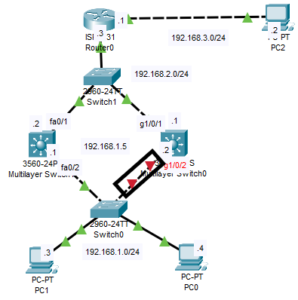
To test if the network will fall back to SW1, I have shutdown the g1/0/2 interface of SW0 and repeated the traceroute command on PC0, and I get the following output:
 C:\>tracert 192.168.3.2

Tracing route to 192.168.3.2 over a maximum of 30 hops:

  1   0 ms      0 ms      0 ms      192.168.1.1
  2   11 ms     0 ms      0 ms      192.168.2.3
  3   0 ms      0 ms      11 ms     192.168.3.2

Trace complete.

C:\>
Step 4: Configuring Preemption
When the g1/0/2 of SW0 is brought back up, SW1 will not give up its role as the active router, even though it has lower priority values. If you want a situation where SW0 will gain back its role automatically as the active router once the interface is brought back up, you need to configure Preemption.
You can configure preemption with the command below;
SW1(config-if)#standby 1 preempt

I am a passionate Networking Associate specializing in Telecommunications.
With a degree in Electronic engineering, I possess a strong understanding of electronic systems and the intricacies of telecommunications networks. I gained practical experience and valuable insights working for a prominent telecommunications company.
Additionally, I hold certifications in networking, which have solidified my expertise in network architecture, protocols, and optimization.
Through my writing skills, I aim to provide accurate and valuable knowledge in the networking field.
Connect with me on social media using the links below for more insights.
You can contact me using [email protected] or connect with me using any of the social media account linked below