Dynamic Host Configuration Protocol (DHCP) is a protocol that dynamically assigns IP addresses to any host devices in a network from a pool of IP addresses configured on the DHCP server.
Although DHCP is traditionally configured on a router or on a dedicated server, a Layer 3 switch can also serve as a DHCP server.
In this post, I will be showing you how to configure DHCP on the layer 3 switch in the packet tracer. The configuration steps are similar to the process of configuring DHCP on a Cisco router; the only difference is that you need to enable IP routing on the layer 3 switch and also turn the switch port to a routed port.
Let’s dive in
Network topology
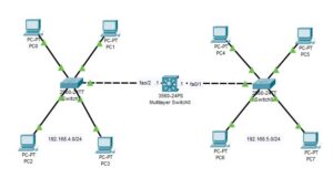
The network topology that we will be making use of is shown in the image below. As you can see, it comprises 1 layer 3 switch, 2 layer 2 switches, and 4 PCs attached to each of the layer 2 switches. In this post, we will be configuring DHCP on the layer 3 switch so that each of the PCs can automatically obtain an IP address from the DHCP server (layer 3 switch).

How to Configure DHCP on Layer 3 Switch
The steps to configure DHCP on Layer 3 switch are outlined below;
Step1: Configure the interfaces of Layer 3 switch.
Because we have only one VLAN each on the fa0/1 and fa0/2 interfaces of the layer 3 switch, there is no need to create an SVI on the layer 3 switch; we will need to turn the switchport into a routed port and then assign an IP address directly on the interface.
Here are the commands to turn the switchport to a routed port and assign an IP address to the fa0/1 and fa0/2 interfaces of the layer 3 switch;

Switch>en
Switch#conf t
Switch(config)#hostname L3
L3(config)#int fa0/1
L3(config-if)#no switchport
L3(config-if)#ip address 192.168.5.1 255.255.255.0
L3(config-if)#no shut
L3(config-if)#int fa0/2
L3(config-if)#no switchport
L3(config-if)#ip address 192.168.4.1 255.255.255.0
L3(config-if)#exit
L3(config)#ip routing
The command “no switchport” turns the switch interface to a routed port, and the command “ip routing” enables IP routing on the layer 3 switch. I hope you are familiar with every other command.
Step 2: Configure DHCP on the layer 3 switch
Enter the following commands one per line to configure layer 3 switches as DHCP servers for the 192.168.4.0/24 network;
L3(config)#ip dhcp excluded-address 192.168.4.0 192.168.4.10
L3(config)#ip dhcp pool Pool_1
L3(dhcp-config)#default-router 192.168.4.1
L3(dhcp-config)#dns-server 192.168.4.1
L3(dhcp-config)#network 192.168.4.0 255.255.255.0
Line 1: Specifies the range of IP addresses (192.168.4.1 to 192.168.4.10) that will not be dynamically assigned to host devices by the DHCP server. These addresses are excluded from the DHCP pool and can be manually configured for special host devices like servers.
Line 2: This command creates a DHCP pool named “Pool_1” and enters the DHCP configuration mode for that specific pool.
Line 3: This command sets the default gateway (router) IP address that will be provided to the DHCP clients.
Line 4: This command sets the DNS server IP address that will be provided to the DHCP clients for domain name resolution.
Line 5: specifies the network address and subnet mask for the DHCP pool. In this case, it’s network 192.168.4.0 with a subnet mask of 255.255.255.0.
Similarly, enter the following commands to configure DHCP for the right network (192.168.5.0/24).
L3(config)#ip dhcp excluded-address 192.168.5.0 192.168.5.10
L3(config)#ip dhcp pool Pool_2
L3(dhcp-config)#default-router 192.168.5.1
L3(dhcp-config)#dns-server 192.168.5.1
L3(dhcp-config)#network 192.168.5.0 255.255.255.0
Step 3: Configure the DHCP Client
Now that we have completed the DHCP configuration on the Layer 3 switch, the next thing is to enable DHCP on the host devices so that it can dynamically obtain an IP address from the DHCP pool.
Tap on each on one of the PCs, and then navigate to the “config tab.” Then enable DHCP as shown in the image below.
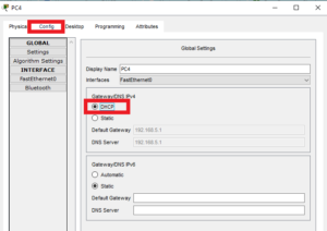
As you can see above, PC4 has obtained its IP address automatically from the DHCP server (layer 3 switch). Repeat the above step on every other PC to get them to obtain an IP address from the pool.
Related content;
How to Configure DHCP Server For Multiple VLANS in Packet Tracer
DHCPv4 Server & DHCPv4 Client Configuration on Cisco Router
How to Configure DHCP on Layer 2 Switch in Packet Tracer
How to Configure DHCP Relay Agent on Layer 3 Switch
How to Configure DHCP Snooping In Cisco Packet Tracer

I am a passionate Networking Associate specializing in Telecommunications.
With a degree in Electronic engineering, I possess a strong understanding of electronic systems and the intricacies of telecommunications networks. I gained practical experience and valuable insights working for a prominent telecommunications company.
Additionally, I hold certifications in networking, which have solidified my expertise in network architecture, protocols, and optimization.
Through my writing skills, I aim to provide accurate and valuable knowledge in the networking field.
Connect with me on social media using the links below for more insights.
You can contact me using [email protected] or connect with me using any of the social media account linked below