The Dynamic Host Configuration Protocol (DHCP) automates the assignment of IP addresses to host devices on a network.
A DHCP pool, which is a pool of the range of available IP addresses, is created on the DHCP server. This server leases IP addresses from the pool to any device with DHCP enabled on the network.
Traditionally, a dedicated server is employed for DHCP; however, various network devices can also serve as DHCP servers. This includes routers, Layer 3 switches, and even Layer 2 switches.
In this post, I’ll guide you on how to configure DHCP on the Layer 2 switch in the packet tracer.

Related Post
- How to Configure DHCP on Layer 3 Switch In Packet Tracer
- How to Configure DHCP Server For Multiple VLANS
- How to Configure DHCP Relay Agent on Layer 3 Switch
Network Topology
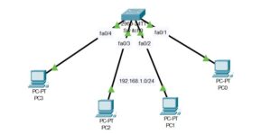
The network topology we will be making use of in this post is shown in the image below. As you can see, it consists of a layer 2 switch and 4 PCs attached to the switch. In this demonstration, we will configure DHCP on the layer 2 switch so that it will automatically lease IP addresses to the PCs once DHCP is enabled on them.

How to Configure DHCP on Layer 2 Switch
The steps to configure DHCP on a layer 2 switch are the same as the steps to configure it on a router or on a layer 3 switch, except that you need to assign an IP address to the VLAN interface of the layer 2 switch.
Here are the steps to configure DHCP on layer 2 switch:
Step 1: Assign IP address to the VLAN interface
In our network, we have VLAN1 which is the default VLAN that exist in every switch. Once host devices is connected to the switch, it will have access to this VLAN. If you have a network having multiple VLANS, you can check our post on how to Configure DHCP Server For Multiple VLANS.

Enter the following commands to assign IP address to VLAN1
Switch>enable
Switch#configure terminal
Switch(config)#interface vlan 1
Switch(config-if)#ip address 192.168.1.1 255.255.255.0
Switch(config-if)#no shut
Step 2: Configure the Layer 2 Switch as DHCP server
Now that the layer 2 switch has an IP address on its VLAN 1 interface, we can configure it as a DHCP server. The commands are as follows:
Switch(config-if)#ip dhcp excluded-address 192.168.1.1 192.168.1.5
Switch(config)#ip dhcp pool MyPool
Switch(dhcp-config)#network 192.168.1.0 255.255.255.0
Switch(dhcp-config)#default-router 192.168.1.2
Switch(dhcp-config)#dns-server 192.168.1.3
Step 3: Configure all PCs as DHCP Client
For each of the PCs existing on the network, go to Desktop>IP Configuration
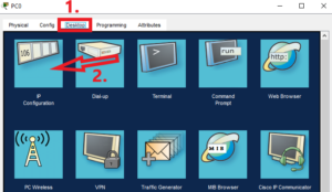
Then enable DHCP, and the PC will obtain an IP address from the DHCP server.
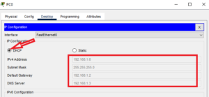
Repeat the above step for each of the PCs existing on the network.
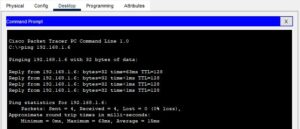
Step 4: Test connectivity
Open the command prompt of one of the PCs and ping the IP address of another PC; you should get a reply.
Here is a video on how to configure DHCP on layer 2 switch;
Related Post
- How to Configure DHCP on Layer 3 Switch In Packet Tracer
- How to Configure DHCP Server For Multiple VLANS
- How to Configure DHCP Relay Agent on Layer 3 Switch
- DHCPv4 Server & DHCPv4 Client Configuration on Cisco Router
- How to Configure DHCP on Layer 2 Switch in Packet Tracer
- How to Configure DHCP Snooping In Cisco Packet Tracer

I am a passionate Networking Associate specializing in Telecommunications.
With a degree in Electronic engineering, I possess a strong understanding of electronic systems and the intricacies of telecommunications networks. I gained practical experience and valuable insights working for a prominent telecommunications company.
Additionally, I hold certifications in networking, which have solidified my expertise in network architecture, protocols, and optimization.
Through my writing skills, I aim to provide accurate and valuable knowledge in the networking field.
Connect with me on social media using the links below for more insights.
You can contact me using [email protected] or connect with me using any of the social media account linked below