In any network with a small number of VLANs, it is feasible to utilize individual router interfaces to handle inter-VLAN routing. However, as the number of VLANs increases, this approach becomes impractical due to the limited number of interfaces available on routers. This is where the concept of a “Router on a Stick” comes into play.
In this article, we will delve into the fundamental concept of a Router on a Stick and then show you how to Configure Cisco Router Sub-Interfaces and use it to facilitate inter-VLAN routing.
What is router on a stick?
A Router on a Stick is a method of inter-VLAN routing that enables a router to utilize a single interface to connect to multiple interfaces on a switch. By creating sub-interfaces on the router, each associated with a different VLAN, it becomes possible to achieve inter-VLAN routing using just one physical router interface.
The Role of VLAN Tagging in Inter-VLAN routing
VLAN tagging involves assigning a specific Identifier, known as a VLAN tag or VLAN ID, to network packets as they pass through different switches and routers.

As introduced in our article on trunkport configuration, there are two different vlan tag protocols: ISL (inter-switch Link) and IEEE 802.1Q (dot1q). But dot1q is the industry standard today.
When a switch wants to forward a packet intended for a particular VLAN, it gives it a tag (dot1q tag) before it forwards it to a router or next switch. When a packet carrying VLAN tags reaches a router or switch, it recognizes the tags and performs the necessary routing operations to ensure the packet is delivered to the correct destination VLAN. This enables different VLANs to communicate with one another while maintaining logical separation.

Network Topology
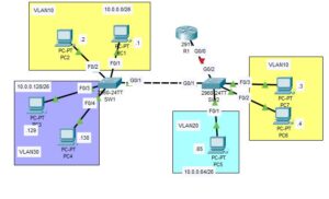
In the network topology shown below, we showcase a simplified network consisting of two switches connected with a trunk link and a router connected to one of the switches with a trunk link. We also created three vlans: vlan 10, vlan 20, and vlan 30 on the switches.
Note: This topology is used for demonstration purposes, and the topology may differ in real-world scenarios.
The main goal of this article is to configure trunk ports on interface G0/2 of switch 2 and then sub-interfaces G0/0.20, G0/0.10, and G0/0.30 on the Router’s G0/0 interface. After this configuration, We will be able to send traffic from one vlan to another.
Note: We had already configured trunkport on the G0/1 interface of switches 1 and 2 in our article on trunkport configuration. So we won’t cover that in this post. You can also check the access port configuration for this network.

How to Configure Cisco Router Sub-Interfaces
We have three VLANs in our network topology, so we will need to configure sub-interfaces for each VLAN on the router. Also, switch 2 is attached to the router using interface G0/2. We will configure trunkport on that interface as well. Let’s take it step-by-step.
1. Trunkport configuration for G0/2 of switch 2
Enter the following command to configure trunkport on the G0/2 interface of switch 2.
SW2>en
SW2#conf terminal
SW2(config)#int g0/2
SW2(config-if)#vlan 10
SW2(config-vlan)#vlan 20
SW2(config-vlan)#vlan 30
SW2(config-vlan)#exit
SW2(config)#int g0/2
SW2(config-if)#switchport mode trunk
SW2(config-if)#switchport trunk allowed vlan 10,20,30
SW2(config-if)#switchport trunk native vlan 1001
SW2(config-if)#no shut
SW2(config-if)#exit
This command on trunkport configuration might not sound familiar to you; we already covered trunkport configuration in detail; check it out.
2. Sub-Interface configuration for Router
Enter the following command to configure the sub interfaces on the router.
R1>en
R1#conf terminal
R1(config)#int g0/0
R1(config-if)#no shut
R1(config-if)#int g0/0.10
R1(config-subif)#encapsulation dot1q 10
R1(config-subif)#ip address 10.0.0.62 255.255.255.192
R1(config-subif)#int g0/0.20
R1(config-subif)#encapsulation dot1q 20
R1(config-subif)#ip address 10.0.0.126 255.255.255.192
R1(config-subif)#int g0/0.30
R1(config-subif)#encapsulation dot1q 30
R1(config-subif)#ip address 10.0.0.190 255.255.255.192
Here is a brief explanation of the above commands:
- We first entered the router’s interface configuration mode and turned it up using the command “no shutdown”.
- Then we entered the router’s sub-interface (g0/0.20) and then used “encapsulation dot1q 20” to assign that sub-interface to VLAN 10. Note: 20 in “encapsulation dot1q 20” is the VLAN ID for VLAN 10.
- We used the command “ip address 10.0.0.62 255.255.255.192” to assign an IP address to sub-interface 10 of the router. Note: This IP address, “ip address 10.0.0.62 255.255.255.192,” is now considered the default gateway of any host on VLAN 10.
- We then repeated steps 2 and 3 above for interfaces g0/0.20 and g0/0.30, and that is all for inter-VLAN configuration.
3. Verify Connectivity
Open the Command Line Interface (CLI) of one of the PCs on VLAN 10 and ping another PC on VLAN 30 to verify inter-VLAN connectivity. The video below shows a successful ping from a PC on VLAN 10 to a PC on VLAN 30.
From the video, you can observe that the packet from one VLAN has to travel through the router before it can get to a PC on another VLAN. This is very much different from what we saw on intra-VLAN communication
Conclusion
With what we have covered in this article, I believe you have learned How to Configure Cisco Router Sub-Interfaces. If you have any questions, do leave them in the beginning section below, and I will attend to them as soon as possible.

I am a passionate Networking Associate specializing in Telecommunications.
With a degree in Electronic engineering, I possess a strong understanding of electronic systems and the intricacies of telecommunications networks. I gained practical experience and valuable insights working for a prominent telecommunications company.
Additionally, I hold certifications in networking, which have solidified my expertise in network architecture, protocols, and optimization.
Through my writing skills, I aim to provide accurate and valuable knowledge in the networking field.
Connect with me on social media using the links below for more insights.
You can contact me using [email protected] or connect with me using any of the social media account linked below