Access ports play a crucial role in connecting end devices to a specific VLAN within a switch. In this article, I will show you how to configure access ports on a Cisco switch using Packet Tracer.
Network Topology
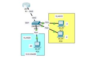
In the network topology depicted below, we showcase a simplified setup consisting of a switch connected to a router. This topology is used for demonstration purposes and may differ in real-world scenarios.
In the topology, We created two separate VLANs, VLAN 10 and VLAN 20, and connected them to the switch. We have also included PC6 and PC7 in VLAN 10, and PC5 in VLAN 20. In this post, I will create access ports for VLAN 10 and VLAN 20.
Step-by-Step Guide To Configuring Access Ports on Cisco Switch
The following step-by-step guide outlines the process to configure access ports on a Cisco switch using Packet Tracer. It should be noted that the actual configurations may vary based on specific network requirements and device models.
Step-1 Configure Router Assign the appropriate IP address to the router.

Step-2 Configure hosts: Assign appropriate IP addresses to all the PCs in the network
Step-3 Create vlans: Enter the global configuration mode of the switch and execute the following commands to create VLAN 10 and VLAN 20:
vlan 10
exit
vlan 20
exit
Step 4: Configure Access Ports for vlan 10: Enter interface range configuration mode and specify the range of interfaces to which you want to assign VLAN 10. Then Set the interfaces to access mode and assign VLAN 10 to them.
interface range f0/2, f0/3
switchport mode access
switchport access vlan 10
exit
Step-5: Create access port for vlan 20:
Enter the following command to assign vlan 20 to f0/1 interface
interface f0/1
switchport mode access
switchport access vlan 20
exit
Step-5(verify connectivity)
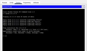
Open the Command Line Interface (CLI) of one of the PCs within VLAN 10 and ping another PC within the same VLAN to verify connectivity.
If the ping was successful, you should see something like this;

I am a passionate Networking Associate specializing in Telecommunications.
With a degree in Electronic engineering, I possess a strong understanding of electronic systems and the intricacies of telecommunications networks. I gained practical experience and valuable insights working for a prominent telecommunications company.
Additionally, I hold certifications in networking, which have solidified my expertise in network architecture, protocols, and optimization.
Through my writing skills, I aim to provide accurate and valuable knowledge in the networking field.
Connect with me on social media using the links below for more insights.
You can contact me using [email protected] or connect with me using any of the social media account linked below